[ Japanese language ]
[ Haas VF-17 ] text & illustration by tw (February 26, 2017)
Haas shaked down the new machine [VF-17].
For the picture of [VF-17] see F1-Gate.com.
I will write my opinion below from the picture of the car body.
Last year's machine the nose tip was low.
This year I extended the center of the tip of the nose to the trends, and raised the left and right within the regulation.
The fact that increasing the airflow under the nose increases the downforce generated at the bottom of the car body was revealed at Tyrrell 019 who made it as high-nose in 1990.
To the height of the middle level of the monocoque side is attached a large canard.
And there should be a border plate of similar area below this.
In the former, the front wing trims up the air flow path that has been bounced up, and the latter regulates the air flow path towards the bottom of the car body.
In this year's technical regulation, you can install a large side deflector.
Since this will move the air flow to the lower side of the car body in large quantities, it is important to make the air flow level with the border plate at the height of the step plane.
The air intake of the side pod is as small as the trend, but this size is determined by the specification of the Ferrari power unit to be installed.
The side pod is surrounded by pod wing. However, before that, there is no S - shaped pod wing which is this year 's trend.
The side pod upper surface sinks from the position behind. It's a classic design like an F1 machine in the 1990s.
Because the new technical regulation lowered the rear wing, the engine cowl is fitted with a shark fin that regulates the airflow during cornering.
One rear wing stay. Swan neck which put emphasis on the lower air current.
Basically, a small team like Haas makes it difficult for a year when technical regulation is changed drastically.
Moreover, only a year has passed since we have entered F1. In that state, it would have been serious to have to develop a very different machine for the following year.
So this year I may not be able to expect much.
However, last year's chassis had a good mechanical finish. If it is based on it well this year, it may be a little better in a course with low aerodynamics dependence.
Romain Grosjean and Kevin Magnussen work for the driver.
(Updated on February 27, 2017)
Photo added to F1 Tsushin.
There is no vertical vane on the upper face of the front wing besides the cascade, so there is still room for development.
In the picture of the car body viewed from above, you can see the angle at which the tie rod retracts.
Therefore, it can be inferred that the wheelbase is somewhat shorter.
There was no cover and brake duct inside the front wheel at the recital. Did not you have enough time?
The middle canard on the side face of the monocoque and the bottom side border plate also have a large area in the front and rear direction.
Perhaps emphasis is placed on the stability of the airflow fluctuation rather than the flow velocity.
The second half of the side deflector consists of two front and back.
For this, I can see the intention of actively fluttering the turbulence that the front wheels will raise.
Air intake position of side pod is a little low.
On the cooling surface, the higher position is not affected by the heat of the road surface.
They also chose the concept of narrowing the side pod side lower part.
At the end of the under plate there is a part that is completely flap-shaped, with air flowing downwards from the top.
This is a new idea and approach, you can see traces of development.
Since there is no groove between the side protector and the headrest, consideration to the air current can not be seen.
Like the Ferrari, the air intake of the induction pod is small.
There are four curved slits in the front area of the rear wheel of the under panel.
The upper arm of the rear suspension is short in width and trendy.
The radius of both ends of the diffuser is large.
The amount of airflow to be squirted is a little, but the behavior change will be calm.
Rear wing The slit at the bottom of the wing end plate is long in the longitudinal direction.
The rear crushable structure has one stay for lifting with a jack at the time of pit in.
I think that it is possible to jack up without this, but it may be meaningful to protect a weak garney at the rear end of the diffuser from breakage.
(Updated May 15, 2017)
Illustrate the aerodynamic device in which both ends of the under panel are in the form of a gap flap as described above.
First of all, the image of air flow course in the top view. The yellow part is a flap shaped part.

In this manner, the airflow on the upper surface of the underpanel is throttled at the side pod side surface and the flow velocity increases.
And the structure is such that a fast air current blows out to the lower side of the flap-like part.
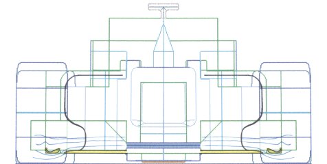
Next is the front view.
Since the under surface of the under panel is at a very low pressure, the conventional machine sucked up the air current from the outside, and the aerodynamic performance was impaired.
Aerodynamic efficiency is good if the air on the bottom surface of the under panel can flow straight from the front toward the Rear as much as possible.
Therefore, VF - 17 creates an air curtain at the end of the under panel by adjusting the arrangement as shown in this figure, and suppresses the air sucked from the outside from the outside to some extent.
It is Haas this season that put a pioneer on this aerodynamic approach. Today the top team is also following it. It's just a hot development area.
According to the current flat bottom regulation, it is permitted to attach an R of 50 mm or less at the end of the bottom of the car body, and this flap shape is made possible by using the clause.
[ Home page ]