2016 F1 aerodynamics design by tw

Design Date : May 5 days from April 22, 2016 / Web Publishing Date : May 8, 2016 [ Japanese language ]

(Text on this page has been translated into English on May 14, 2016, was written in Japanese by May 8, 2016.)

By site writer, aerodynamic design of this year specification.
(Embarrassing a poor sketch)
This is what I've created, and print out the F1 machine design templates, and scan to PC and sketch.
Line of green and blue, and range of body work regulation, the restricted area.

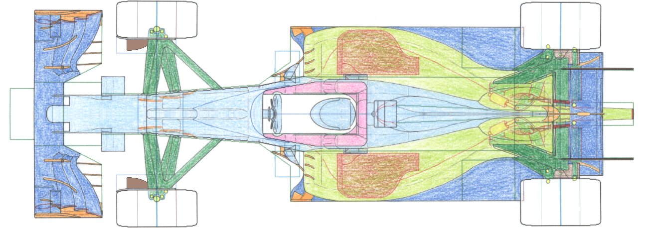
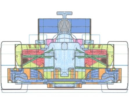
on the upper side of the pitching controller, was passed through the steering shaft.
Accordingly, the steering shaft so as not to interfere with the monocoque, provided bulge monocoque upper surface.

The advantage of this idea :
(1) Using a regulation to maximum, that to increase the foot box underside up to the maximum.
(2) The foot box top surface, specializing in aerodynamics, be a smooth shape.
1 and both of 2, can at the same time.

The disadvantage is that the operation of the front suspension is lowered slightly.
This time was packaged in priority ideas aerodynamics.


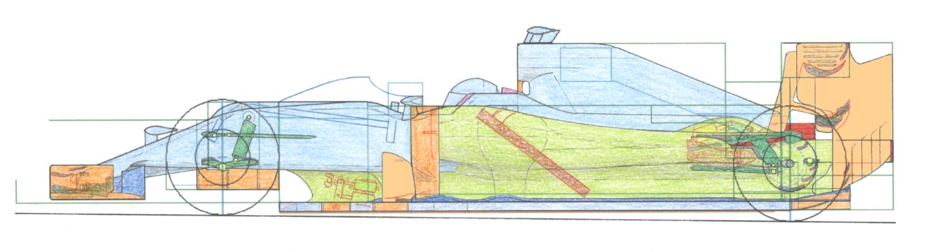
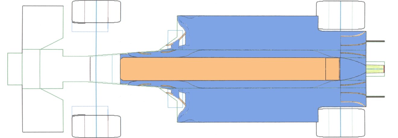
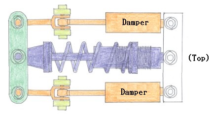
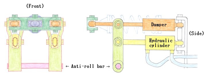
Rear suspension, were placed only three parts to the rear.
(1) Torsion bar.
(2) Hydraulic cylinder.
(3) Bellcrank to operate them.

To the unit that was placed in the front, Hydraulic is connected.
(Front and is that the monocoque bottom of the separator.)

In 1995, Tyrrell is made to appear the hydro-link suspension, I did it to hint.

To use it, but if that can not be placed in the rear end.

Exhaust pipe, passes through the gear box casing.
It orders not to interfere with the rear of the components.

These results, on the upper surface of the rear diffuser, would pass through the high-speed airflow!
The rear of the huge space, watch in the rear view of the right side of the screen.

Under panel and diffuser, to contribute most to the aerodynamics.


Rear suspension unit.
Monocoque bottom, and built-in to the separator.

Deep blue : pitching control.

Hydraulic cylinder to move the bell crank, to expand the stroke, move the damper.
This damper is controlling the right and left rear wheel

Was placed in the center is, but pitching control.
Structure on, the stroke is longer than the left and right of the damper.
Therefore, it is possible to freely set the preload of the coil spring.

Anti-roll bar which is directly linked to the hydraulic cylinder, operated looks good!


[ Home page ]