2017 specification F1 aerodynamic design by tw
Design date: Between 7th December 2016 and 4th January 2017.
Web release date: January 5, 2017.
(Japanese language)
This is the F1 aerodynamic sketch of this year which I designed this year.
However, it is a preliminary version as it does not yet know the detailed area of regulation.
This printed out the author's F1 machine design template, sketched and scanned to the PC.
The green and blue lines indicate areas of the bodywork regulation or areas of restriction.
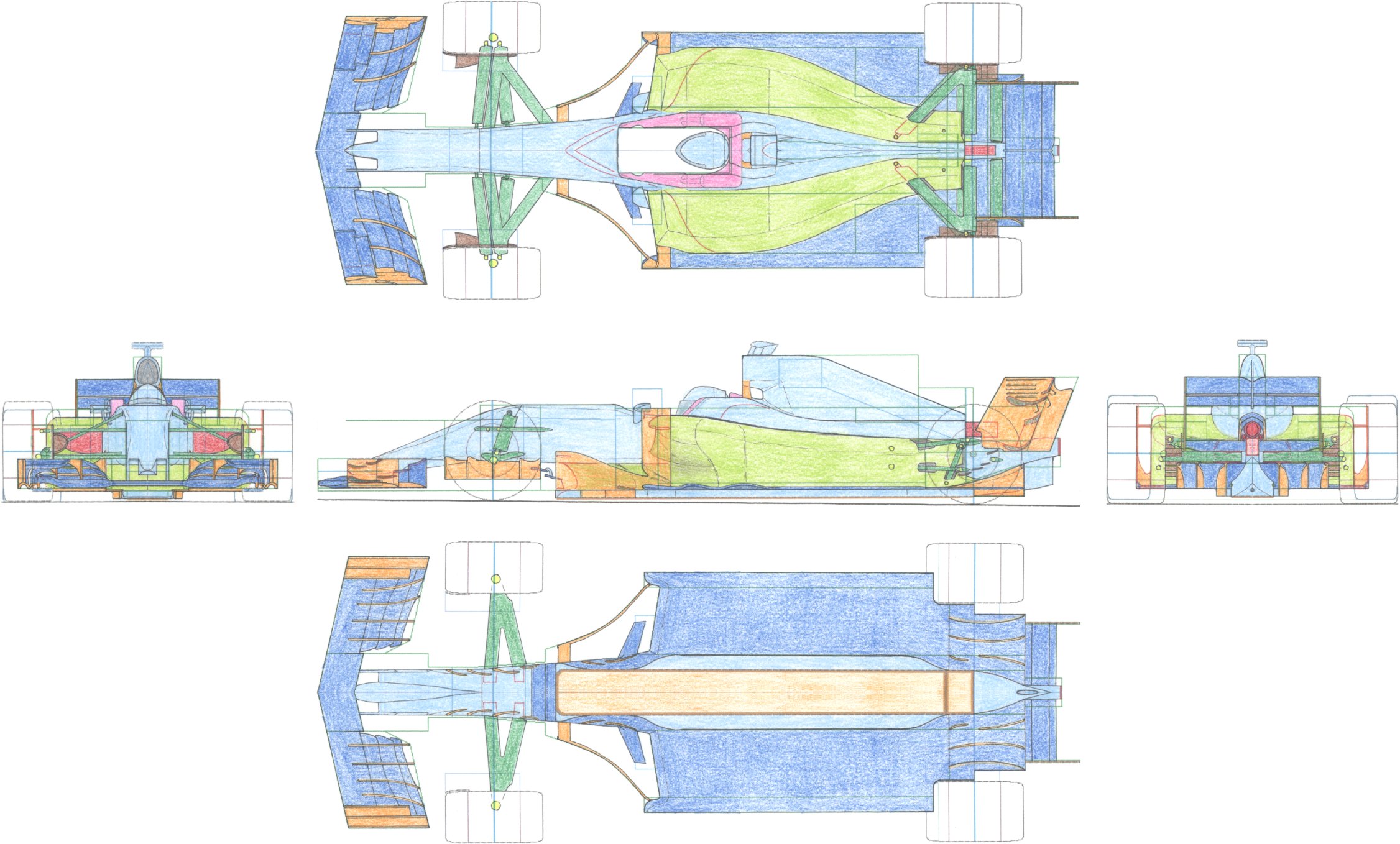
After working, I regretted raising the rear end of the side pod. It's a great failure!
The rear end of the side pod should be lower than the drive shaft.
Since the upper stage of the rear wing becomes lower this year, the aerodynamic effect of lowering the side pod becomes remarkable.
With the new provision, the under panel can be wider, so widen the width of the side pod bottom.
In a wide under panel, if the side pod is narrowed, the sealing performance of the air current to the bottom surface of the vehicle body is deteriorated.
Perhaps the central part of the diffuser of this year's F1 machine will have a shape similar to the one I made this time.
This part of each team is an attention point this season.
Rear wing We did not know the provision of the wing tip plate, so we provisionally set it to be short vertically.
If it is permitted, it would be more advantageous to be longer vertically.
There is an option to exhaust heat from the side of the side protector, It has a possibility of adversely affecting the lower rear wing, so it was closed in this sketch.
[ Home page ]