(Front wing bottom view omitted from the convenience of time and energy.)
2017 specification F1 aerodynamic design(Ver.3) by tw
Date of design: The period from April 1st, 2017 to April 15, 2017.
Web release date: April 19, 2017.
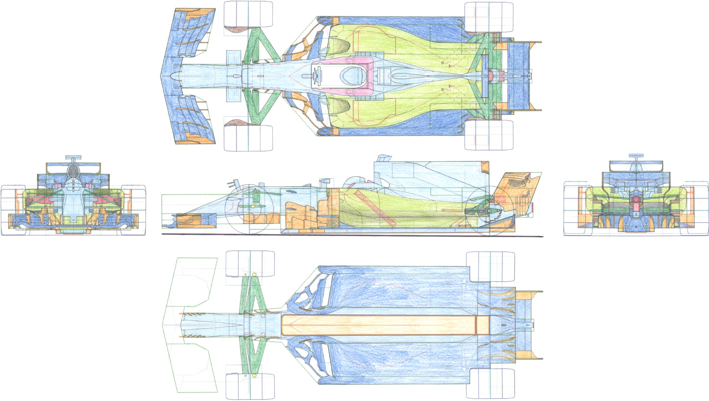
F1 machine aerodynamic design / sketch of this year's specification by the author.
This printed out the author's F1 machine design template, sketched and scanned to the PC.
The green and blue lines in the figure below indicate the range of the bodywork regulation and the area of restriction.
The biggest difference between the previous work and this work is that I designed it after watching the machines of each team this year.
For that reason, I have incorporated some effective ideas that are seen in this year's new machine.
Front suspension was made high mount by stretching out his arms from upright.
However, different from this year's Mercedes and Toro Rosso, it was a geometry that lowered the roll center height!
Since the area where the side deflector is permitted has also been found out, we made maximum use of it and equipped with middle border wing.
The lateral flap with a height of 50 mm at the front of the side of the step plane spread out from the center line that should be the maximum allowable in this area to 250 mm.
By providing an air intake on the side pod upper surface, we reduced the lift which was conventionally generated in this part, and increased the flow rate of the undercut.
The shark fin was equipped with a T wing on the second floor, which made a balance between aerodynamics and strength.
The exhaust heat port of the side pod was set high, and the lower arm of the rear suspension was set at the same height as the drive shaft, and the air flow on the upper surface of the diffuser was cleaned.
(Front wing bottom view omitted from the convenience of time and energy.)
[ Home page ]