[ Japanese language ]
[ Ferrari SF70H ] text & illustration by tw (February 24, 2017)
February 24, 2017, Ferrari announced the 2017 year machine "SF 70 H".
For a picture of this new car, see F1 Tsushin.
Below, I will write my opinion from the overview of the car body.
The nose at the center of the tip of the nose is careful to increase the airflow supply under the nose by separating it into the lower side and side as much as possible even a little air flow.
It is a true opposite approach to Mercedes' nose.
The airflow in contact with the lower surface of the nose is sucked into the nose hole of the S duct, which is expelled upward.
In this way, the kinetic energy of the air flow under the nose is not damaged.
Three straight splitters are installed under the front wing, and the air flow path to the front wheel is cleaned.
The front wheel brake duct was a common sense size, and the intake was partitioned a lot by the lateral fin.
This is a contrivance to prevent rubber that falls on the road from entering the intake.
Three narrow canards were installed at both ends of the upper surface of the monocoque.
This is the purpose of controlling the airflow path that the front wing jumps up.
This year's new technical regulation seems to have increased the range of construction permitted in this area.
In the new machine up to the present time, the shape of the border plate just before the bottom of the side pod was revealed for the first time.
What made this modeling possible is a byproduct of being clearly permitted to wear side deflectors.
Side deflectors are a relatively low class.
However, it can be seen that the area of the bottom plate area is trying to make full use of the new technical regulation.
Like Renault and Mercedes, there is a vertical large plate diagonally in front of the pod wing.
Because this has two horizontal slits cut off, the airflow in this area should be moving in the vertical direction.
Otherwise, there is no point in making gap flaps.
Border fin at the tip of both ends of the under plate has a two-stage structure to split the air current.
The most distinctive feature of SF70H is the air intake of the side pod and it became a very original shape!
The horizontal area of the pod wing before it has a two-tiered structure consisting of an upper element and a middle element.
The airflow that passed through the pod wing is finally filled into the air intake of the side pod.
The inside of the front end of the side pod opens its mouth upwards and the air flow course of this part is still wrapped in a mysterious veil ...
The opening of the side pod intake is small, so the amount of air flowing to the side pod side seems to be quite large.
This shields the air current that the bottom of the car body was supposed to absorb from the side, and contributes to downforce generated at the bottom of the car body.
The coke bottle is narrowed down rapidly, and it is possible to see the intention of giving a strong kinetic energy to the upper surface of the diffuser.
The induction pod is an orthodox shape.
Mid Wing with the same width as the camera is worn.
On the upper rear end of the wider area of the shark fin there is the same type of thin wing that Mercedes wore when traveling yesterday.
Since this is seen in the blade section in the lift direction, this single unit does not generate downforce.
There is a high possibility that it is a device that directs air current to the rear wing much.
When rewritten to this year's new technical regulation, there may be some clauses of the height and width of the rear wing until last year.
The aerodynamic effect of this wing would be to combine the vertical sharp fin and the transverse thin wing and direct the air current to the rear wing.
In the upright side attachment position of the upper arm of the rear wheel, the upright extends slightly inward, keeping the length of the upper arm short.
This is probably due to demands from geometry, such as camber change.
The rear wing stay is a swan neck, cherishes the lower air current with high aerodynamic contribution.
However, it is doubtful that the stay is not one, but two. This will purely increase frictional resistance and interference resistance ....
Below the rear wing there is a monkey seat.
On the rear part of the wing tip plate can be seen a vertical garney.
The SF 70H is a machine that the racing funs want to expect this year because it can be seen the aerodynamic concept that creatively attacked.
Although concrete aerodynamic performance can not be judged until a photograph capturing a key point comes out, it must be a very interesting machine.
The driver continues to be a combination of Sebastian Vtertel and Kimi Raikkonen.
(Updated on March 28, 2017)
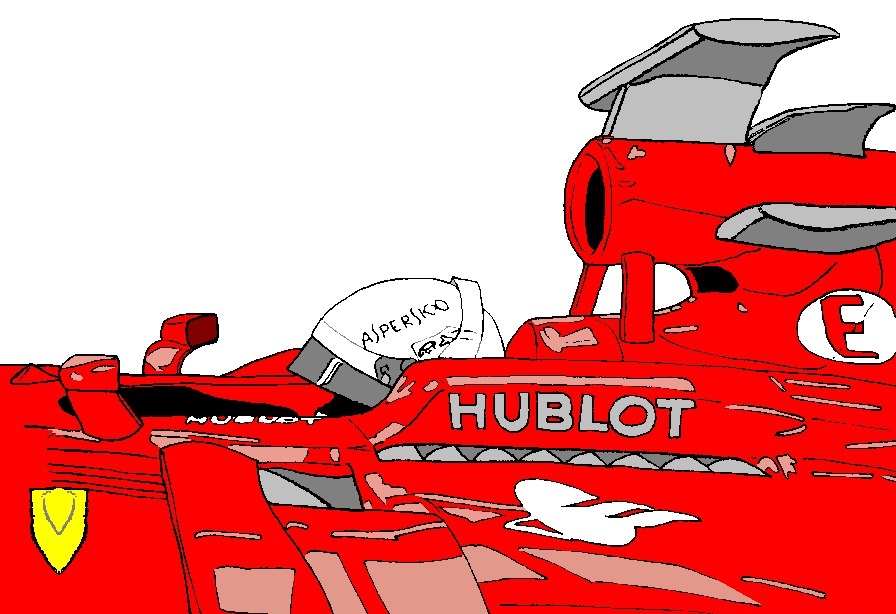
With the pit of the opening game, the structure of the top side pod of SF70H turned out.
The opening of the top surface of interest is structured to take airflow from the upper side to the inside of the side pod!

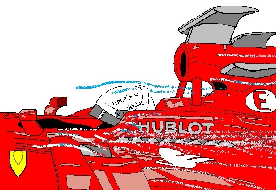
When adding an air current image, it becomes as follows.
(The blue part of the airflow line indicates the low pressure region, and the red part indicates the high pressure region.)

Even if an opening is provided on the upper surface of the side pod without devising, air flow is difficult to enter the intake.
Air flow has the property of flowing from high pressure to low pressure.
Because the heat exchanger is inside the intake, the pressure of the air flow increases.
However, in the current Formula 1 machine, the front part of the steep angle side protector is high pressure.
Furthermore, exhaust heat conducted outside the side protector is also slow in flow rate and high in pressure.
This high pressure area serves as the resistance of the wake in the upper opening, and the SF70H can fill the air flow into the upper surface intake.
Currently, the side pod upper surface of another machine is a shape that accelerates the air current. In this case, a lift will occur.
However, by using a part of the upper surface of the SF70H as an air intake, the aforementioned lift does not occur.
Rather, at the SF70H, might get a little downforce.
In addition, the front part of this upper intake should contain the upper element of the side impact structure.
This year's Ferrari is a unique and creative aerodynamic design. It's a fun machine for the future.
[ Home page ]