[ Japanese language ]
[ Force India VJM10 ] text by tw (February 23, 2017)
February 22, 2017, Force India's 2017 machine "VJM 10" was announced.
See the picture of the machine, F1 Tsushin.
Let's write my opinion below from the overview of the car body.
Nose abolished "nostrils" which was the most characteristic until last year, but this time it was a different form of "new nostrils".
It is located in the center of the tip of the nose, a considerably long knob in the front and back, and the bottom plate on the left and right.
This forms a "nostril hole" in effect.
There is some sort of thing like air flow which enters here probably discharges to the lower side of the nose side face.
The aim is to supply more air flow to the lower part of the car body.
As a result, downforce occurring on the bottom of the car body excellent in L/D increases.
The flap of the front wing is quirky, and there is a section where the upper part of the left and right is depressed in the letter V.
This may be adjusting the condition of the air current colliding with the front wheels inside and outside of the V character.
The front suspension unit is covered with a cosmetic cowl. The top of the nose became stepped.
This makes it possible to set the angle of the push rod, which is excellent in the operation / responsiveness of the suspension.
Because of the convenience of "new nostrils", no nose hole (S duct) is found.
The distance between the upper and lower wishbones of the front suspension is short.
Although the rigidity of suspension is disadvantageous, it is excellent in aerodynamics.
When the lower arm position is increased, the lower air flow can be made more clean, so that it contributes to downforce generated on the bottom of the vehicle body excellent in L/D.
Is there only the narrow narrow hole in the gap between the tire and the upright cover for the front wheel brake duct?
The side deflector is a gap type consisting of at least 5, preventing peeling inside the deflector.
Although it is thinner than Renault yesterday announced, the thickness of the front edge of the under plate of the side pod is large.
Here, the separator at the bottom of the monocoque seems to flow into the bottom of the underplate, separating the airflow separately to the left and right.
The upper of the side pod's pod wing is wide. The side is cut short and it turns inward.
In other words, the pod wing is not connected to the lower under plate.
Following the "new nostril" with VJM 10 is the side protector and packaging at the bottom of the induction pod.
The side protector is a form that pushed forward the type of Red Bull of last year aggressively.
There is a "groove" between the headrest and the side protector, and the airflow passes from the left and right of the helmet to here.
And when the rear part of the side protector looks from the side, it becomes a rounded cliff wall.
At the rear part of the cliff, when viewed from the top, the airflow from the left and right headrests and the airflow outside the protector join.
This will cause delamination and turbulence. Instead, it is possible to suppress the occurrence of lift due to the high flow rate on the side protector upper surface.
To realize this, the area of contact between the rear part of the helmet and the headrest is very small.
Therefore, it will be possible to replace the aerodynamic attached parts at the rear of the helmet with a special made narrow rear part.
As a consideration of this type, it was necessary to make the entire lower part of the induction pod intentionally spread.
If the width is narrow here, the air flow to the rear wing can not be adjusted without restricting the turbulence generated at the rear of the side protector.
As another consideration, the interference resistance inside the helmet and side protector will be quite large.
However, as the driver tilts his head during cornering, "airflow path switch" is realized.
When the helmet contacts the side protector, it seems to be able to stop supplying the air flow in one groove and increase the air flow rate in the other groove.
The air intake opening area of the induction pod is small, and there seems to be no secret in particular.
Engine cover is a wide shark fin.
Due to the aerodynamic structure of cliffs and grooves, if the shark fin does not reach the base of the engine cowl, the air current may become unstable.
There is no slit of the under panel behind the rear wheel which was popular last year.
The position of the upper and lower wishbone of the rear suspension is high and it is a standard shape of the pull rod type.
There was a big change in technical regulation this year.
In such a year of change, racing machines tend to be full of ingenuity. It is a very interesting year!
Sergio Perez and Esteban O'Con serve as drivers.
Updated May 22, 2017
The most characteristic area of VJM 10 is "nose hole nose", but the detailed shape has not been found yet.
So in order to touch on this site, the second characteristic area in VJM 10 is the "deep groove" between the side protector and headrest.
To say what this means, I'm sorry for bad illustrations, but I will write down below.
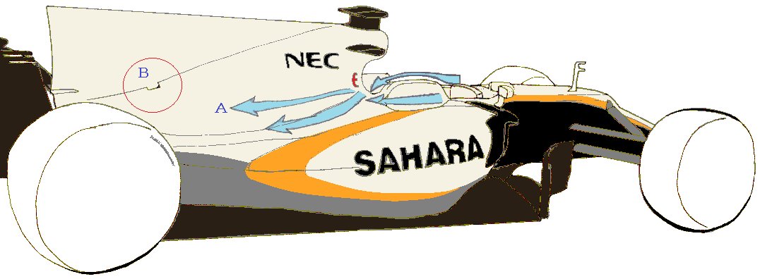
Here the flow on the top of the side protector is not very important.
At the core of the aerodynamic concept is the flow path that hits the side of the induction pod of "A", where the air hit the front of the side protector flows sideways.
Points pass between the inside of the side protector and the helmet, where the air flow goes to Rear without moving up and down.
Here, the fact that the air current does not move up and down means that its components do not produce lifts nor downforce.
If such an aerodynamic design is adopted, interference resistance will occur when passing between the inside of the side protector and the helmet, but suppressing the occurrence of negative lift due to the air current being narrowed on the side protector upper surface as in the past There is an effect to do.
The aerodynamic design that makes a groove between the side protector and the headrest remembers McLaren in 1996 as the first time, but the design that thoroughly prevents the lift of the side protector from being thoroughly confirmed is the design of VJM 10 I think that it was not before.
However, the lower end of the induction pod of VJM 10 is slightly wide.
Air flow which passed through the groove between the side protector and the head rest tends to be disturbed.
This is done because it is necessary to rectify the air flow toward the rear wing by narrowing the air current by making the lower end of the induction pod wider.
If it is the lower end of the wide induction pod, the air resistance increases accordingly.
Here is the reason why this "deep groove" approach is not simply an advantage.
Still, Force India's aerodynamics development team is striving to reduce negative lift dargs here.
"B" is a mystery hole also in Mercedes of Works. It is probably exhausting heat.
But what does it mean that the hole does not open horizontally backwards, but opens diagonally upwards?
Perhaps there is a small whirlpool wound around the waste heat at the edge of the rear end of the hole, and it may be used for the aerodynamic force of the late flow, is it?
[ Home page ]