[ Japanese language ]
F1 machine aerodynamic design for 2018 year by tw (The second one)
(Design day: From December 2017...
Web release date: January 14, 2018) |
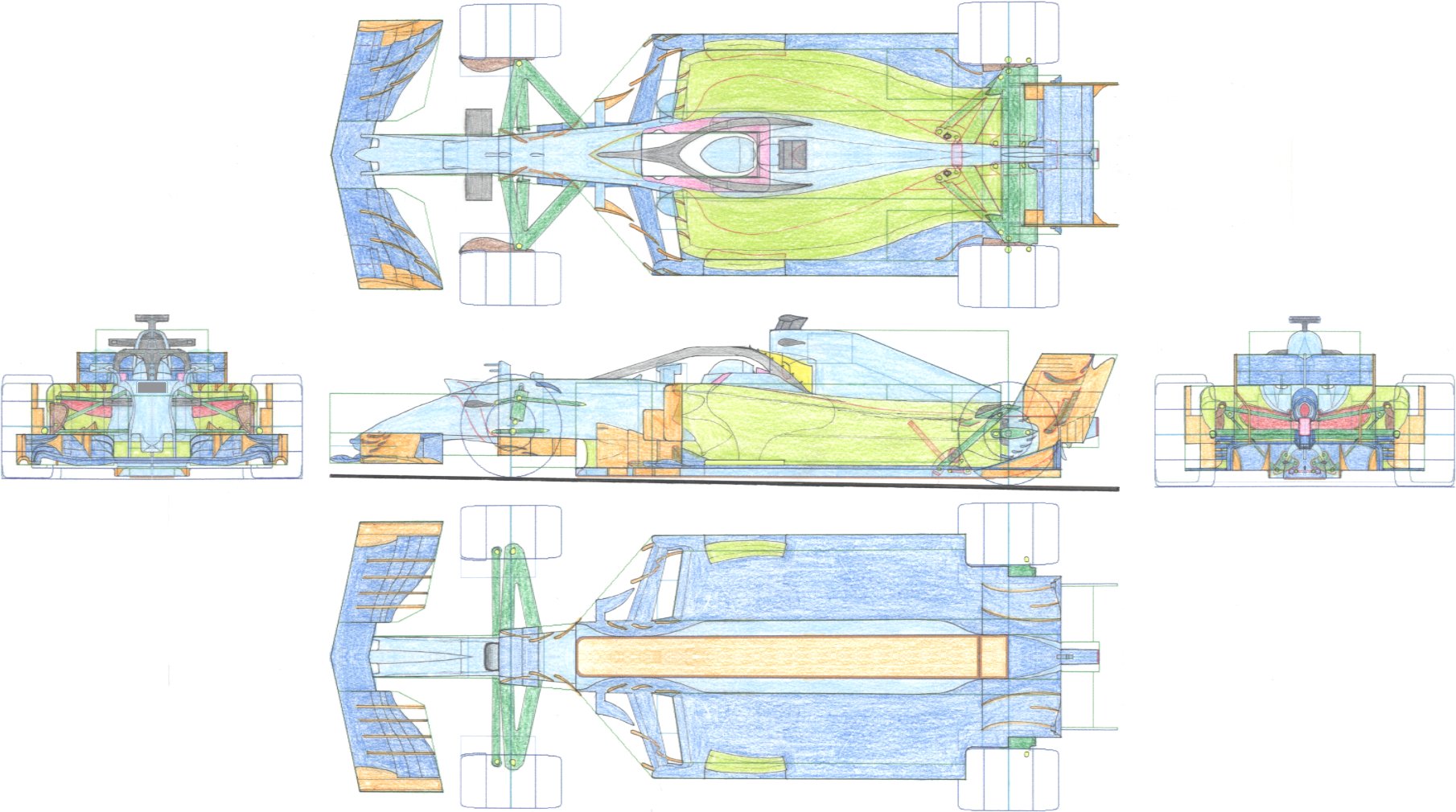
This is the F1 machine aerodynamic design / sketch of the 2018 season specification by the author.
In this sketch I painted the F1 machine design template printed out.
Green and blue lines indicate areas of bodywork prescription or restricted areas.
The sketch below is the specification of Max downforce with Monaco and Hungary in mind.
At the moment, permission for the aerodynamic addition of "halo" seems to be within 20 mm from the top of the halo.
In that case, my author's design will be scrapped.
But instead, the black line drawn as a shadow and the line of a small swirl generator will survive.
If there are loopholes in the terms of the halo, the yellow structure will be effective and the left and right air currents passing through the halo will join in the rear.
The nose hall has been approved as a flow path to pull airflow from the bottom up in the current machine.
If it is interpreted aggressively, the flow path leading from the upper side to the lower side should also be legal.
For this reason, this work supplies airflow downward from the top of the nose, contributing to an increase in downforce on the bottom of the car body.
It is also intended that you do not want high-speed airflow to halo. You can see by looking at the side view.
I want to guide the airflow straight rearward with the lower surface of the front wing. (For the air flow course of the underbody.)
However, on the upper surface of the front wing, we want to direct the air current to the outside. (To avoid disturbance.)
For that reason, it is in the form of such upper and lower splitters.
Long ago, the brake ducts of the front wheels are blocked with gummed tape during rainy weather (low temperature) to limit the opening area.
For this time, we designed the line of the duct top view so that it conforms to the shape that the gummedape has influence.
The shape of the deflector on the inner side of the front wheel is different on the upper side and the lower side, but since it is a bug, please pardon me. The bottom side is correct.
The rear end of the side pod upper surface was made higher than the upper arm of the rear suspension.
This corresponds to a low downforce type spoon-shaped rear wing shape.
Since the opening area of the rear part is related to the exhaust heat quantity, it can be made narrower than the above figure except for Monaco and Hungary, and air resistance can be further reduced.
The structure of the anti-roll bar of the rear suspension is easy to understand when viewing the side view and the rear view.
(Last updated date of this page: January 14, 2018)
[HOME Page]