[ Japanese language ]
[ Mercedes W08 ] text & illustration by tw (February 24, 2017)
On February 23, 2017, Mercedes' new machine "W08" was released.
For the photo of "W08", see F1 Tsushin.
I will write my opinion below.
Nose tip low. It is the same type as last year, there is no Cobb in the center.
I am wondering about the low nose of Mercedes since 2015.
It is a very mystery how I can secure the downforce generated on the underside of the body with this.
A large nose hole (S duct) is open on the top of the nose, and it activates the air current under the nose.
For the front suspension, the front upper arm was raised to near the top of the nose to increase the lower arm.
The package of the S duct and the high mount / front wishbone is a package that emphasizes the downward flow of the front package.
But why do not you devise a way to raise the nose?
This year there is no team to high mount the nose side camera. It may have been limited by new technical regulations.
Because it might be for testing, Pitot sensors on the nose has three sensors.
The side deflector is tall. The upper edge has three levels.
The deflector area is wide overall and you can see how you are trying to make the best use of the new regulation.
At both ends of the monocoque, a boomerang shaped canard is arriving and stands out.
In my opinion, the upper Canard is not important.
The real aim of this aerodynamics is on the lower side.
There should be an area border plate that projected the above canard downward!
(Otherwise, you can not pass the flat bottom regulation.)
The engineers should be ambitiously working on the airflow flowing down the car body in this part.
This year, a vertical canard stands in front of the rear view mirror.
This also shows that there is a border plate downward.
The rear view mirror has become a cut spoiler and cuts out a mass of air behind the mirror.
I have sketched this idea in February 2002.
The area of both ends is wide in the pod wing in front of the side pod.
In front of this pod wing, two more vertical fences stand upright, only the upper half.
This is also the case for Renault of the other day, so this part is the key point of this year's aerodynamics.
The reason why only the upper side is a vertical fence is because the lower side interferes with the side deflector.
The side deflector directs the airflow outward, but at that time the airflow entrains up and down the deflector.
This is the effect of the turning vane.
In W 08, the air current entrained in the upper side is applied from the middle to the inside of the vertical fence by the upper half.
Here the airflow is throttled and it supplies fast flow to the side pod side of the rear part.
The top of the side pod is high. It seems to be about 600 mm from the reference plane, which is the maximum of regulation in this area.
The air intake of the side pod is a little lower position. After that, the air current is narrowed upward.
Pod wing covering the front end of the upper side of the side pod has short front / rear length.
Here, since the fast flow acts on the atmosphere, the lift force may strengthen.
The air intake opening area of the side pod is extremely small!
With this internal / ventilation volume, we are convinced of the small rear end of W08.
From this opening area, it can be seen that the power unit is operating at a considerably high temperature.
Of the running resistance of the machine, the air resistance increases approximately with the square of the speed.
Therefore, it may be advantageous to make the radiator compact at high speed range.
Simple things become a problem here. Whether the power unit will not fail or not.
It is a simple principle that cooling is more reliable.
Therefore, the result of developing a power unit capable of operating at high temperature directly affects the aerodynamic performance of the machine.
Another characteristic feature of the side pod of W08 is that the upper side of the coke bottle line is squeezing in two stages.
It is an image that McLaren was redesigned in contemporary style in 1989.
If you want to keep fast flow to the rear, one action is better for narrowing down the line
In W08, the bottom coke bottle line is one action.
At the top, it is squeezing in two stages and adjusting the air pressure.
The rear part of the side pod is slightly lower than the upper arm of the rear suspension and emphasizes the efficiency of the rear wing.
The coke bottle is narrowed narrowly enough to worry about waste heat.
This can not be realized unless the routing of the power unit and the exhaust pipe is compact.
Honda who struggled to recover was originally claiming the size zero concept.
The thing that should be emphasized originally is to contribute to the compactification of the coke bottle like Mercedes.
On the under plate behind the rear wheel a lot of slits popular in the last year have been cut.
It is acting on the air current entering the underside of the car body.
The side protector and the induction pod are conservative designs.
The same as last year, the shape of the air intake of the induction pod is retracted at the bottom.
At the present time the shark fin is not wearing.
The camera on the induction pod side is the same as last winter, it is thick.
The rear suspension is a pull rod. The front and rear spans of the upper arm are short.
This prevents the airflow at the rear portion of the side pod upper surface from being disturbed.
When lowering the rear part of the side pod, if the front upper arm of the rear is lengthened, the air flow to the rear wing is inhibited.
The track rod of the rear suspension has approximately the same position as the drive shaft. It has a slightly longer blade section in the front and back.
If the regulation has not changed, the aspect ratio is 3.5: 1.
(Going back to the predecessor of this team, they will be Brown GP, Honda, BAR, Tirel.
In 1996 when it was Tirel, the front and rear suspension arms were made up of thin plates and aimed at the aerodynamic effect.
After a while, the ratio of 3.5: 1 ratio was set for the cross section of the suspension arm.)
The upright of the rear wheel has a large amount of flaps.
In order to prevent interference with the air flow that the flap springs up, the wing end plate of the rear wing curves vertically.
Vertical structures can be seen in the center of the exhaust pipe.
This may be a plate that prevents the exhaust pipe from breaking.
There is a possibility that the rear wing stay passes through the exhaust pipe like Toro Rosso.
The diffuser is fitted with a larger garney lip in the range that can be attached by regulation.
Since the central part of the diffuser is curved and lowered, it has two gurnies attached.
One in the main up sweep part.
The diffuser side warps greatly outwards, so it's two Gurneys.
The rear wing is a 3D shape with its edge rising, reducing the occurrence of tip vortices.
But why will not it be the stay of the Swan neck which put emphasis on the downstream?
The rear part of the wing tip plate of the rear wing has a small curve for the purpose of directing the air flow even a little to the rear side of the rear wheel.
The DRS actuator is small and has low air resistance.
The driver is a combination of Luis Hamilton and the newly joined Balteri Bottas.
(Updated February 25, 2017.)
F1 Tsushin added a photo that details W08.
The upper arm of the front suspension is higher than the apex of the front wheel!
It connects to the upper arm diagonally upward from the upright using the curved connecting parts.
Such a structure has been done in the recent rear suspension, but it will be the first time at the front desk.
With this, it is possible to make the front wishbone high mount, improving the flow of the lower part of the car body which contributes greatly to aerodynamics.
The camera on the side of the front nose is not in direct contact with the side of the nose.
It is supported by parts that extend the camera slightly sideways (two front and rear stays, the middle is a hole shape).
This reduces the growth of the boundary layer at this part more than before and improves the kinetic energy of the air flow toward the rear.
A small canard is visible at the middle position of the monocoque side face.
Since it looks downwards, it should help to supply the air current to the bottom of the car body.
The bottom side of the side pod is apparently the same as McLaren, keeping it narrow.
(At this moment I am skeptical about this method.)
For the thin T-shaped wing just before the rear wing, please refer to the page of Ferrari SF70H.
(Updated on March 17, 2017)
In the Barcelona test, I was experimenting with a new idea to chimney the shark fin of the engine cover.
Since this heat is exhausted to a higher area than the rear wing, even if the exhaust heat flow disturbs the rear, there is not much harm to the aerodynamic performance.
It is a new idea to make this part chimney, but the same form was adopted by McLaren in 1995.
In 1995, there was technical regulation to limit the ram pressure of the engine intake air.
The machine had to have a hole of a defined area above the air intake tube, but McLaren used it in reverse.
The MP4/10 was made into an engine cowl shape like this Mercedes W08, and a 500 mm wide midcenter wing was attached to the rear part.
High pressure air was discharged from the ram pressure cancellation port, it passed the upper surface of the midwing, and contributed a little to the downforce.
Since air has a nature flowing from high pressure to low pressure, when the mid wing is resistant, there was also a function to apply a slight ram pressure to the engine intake air.
In the area similar to that midwing, there were several machines wearing T wings this winter, but Mercedes first released T wings.
I think that Ferrari has released a car with a T wing delayed by half a day or a day, but it is impossible to copy in this time, so Ferrari would have noticed the loophole in the same rule as Mercedes.
In this winter, Mercedes also tried things that made the T wings double.
When looking at the picture, unlike Ferrari, Mercedes is a downforce-generated wing shape, and it is interesting that even though utilization of the same area, there was a difference in the way of thinking.
In this winter joint test, Ferrari's fastest lap was faster than Mercedes' fast test lap.
However, there are rumors that Mercedes had trouble with the engine and was not able to make it 100% output mode.
If so, Mercedes may be leading this year if he recovers from the trouble, but still it may not be Mercedes' run away like the past few years.
Both Ferrari and Red Bull are launching very aggressive machines and it is difficult to predict power unit development competition because the token system of power unit development has been eliminated from this year.
(Updated on March 31, 2017)
This is a comparison chart of the normal suspension arm which I sketched until last year and the High Mount Wishbone this season.
The yellow area in the figure below contributes to the aerodynamic performance of the important lower vehicle body surface.
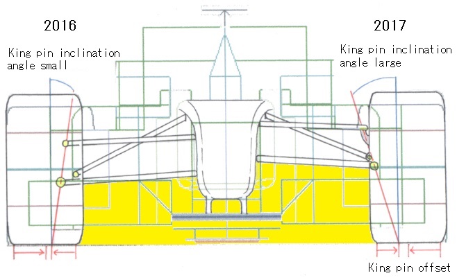
If you look at the area of the yellow area, you can see how effective this is the High Mount Wishbone of this season.
In fact, near the tire, there is a turbulent flow which is evoked by rotation, but it is purified by the deflector.
However, the High Mount Wishbone has some adverse effects on the performance of the suspension.
First, the kingpin must be designed to be close to the installation center of the tire.
(King pin: a line connecting the tire side pivot of the upper and lower wishbones)
Otherwise the kingpin offset increases, the steering force increases, the power consumption of the power steering deteriorates, and the straightness is also adversely affected.
Therefore, in W 08 the kingpin tilt angle should have been made large so that the kingpin offset does not become big.
When the kingpin tilt angle is large, since it changes to the positive camber on the outer tire during steering, W 08 can be inferred that the caster angle is made large.
(The larger the caster angle, the more it changes to negative camber during steering.)
And, as can be seen from the figure, the tread change at the time of stroke increases as the wishbone is short.
Like this, High Mount Wishbone has a very advantageous aerodynamics, but mechanical harm is great.
Do not forget that the center of gravity simply increases.
Still high mount Wishbone was adopted because the aerodynamic performance is important in F1 now.
(Updated May 12, 2017)
This Spanish Grand Prix. At the Barcelona circuit, the degree of aerodynamic performance contributing to lap times is very large, so each team brings aerodynamic updates here every year.
Mercedes, whose title battle with Ferrari is approaching, also has greatly updated aerodynamics this time.
First, the nose cone was made a little narrower just before the mounting position with monocoque.
And, I installed curled large fins in the space next to the nose that was born by narrowing the width.
This is a contrivance to use the longitudinal vortex intentionally generated inside the front wing flap in a more convenient form towards the lower part of the rear body.
This curled fin seems to be integrated with the turning vane which became more solid shape under the monocoque.
The shape is stiff and there are marks that were closely studied in CFDs and wind tunnels.
With the introduction of curled large fins and three-dimensional turning vanes, the airflow course of the front section will be changed to radicals.
Immediately after that, an M-shaped high pressure flap is provided, and the air current is directed downward to the vehicle body.
(See the page of RedBull RB 12 for the mechanism of this flap.)
In the monocoque side area, it seems that the triple pod wing was refined and the side deflector was improved.
Triple pod wing is less radical, but more refined shape than before.
Since the lower portion of the side deflector also acts in a direction to blow off the air current to the outside of the car body, the pod wing draws a curve corresponding to it at the bottom and the air stream is directed straight backward at the top. They came to do this more aggressively.
The reason that the upper portion is straight is to "cut off" the turbulence generated by the rotation of the front wheel and adjust it to the rear and let it flow.
The pod wing is learned by theory, and it has a wing section that makes the outer surface low pressure and the inside high pressure.
The pod wing consists of three pieces, but the second one curls at the lower end and extends to the rear.
This is because the side deflector separates the air flow up and down, so we control the course of the flow that has entered this upper side.
Since this affects the flow direction of the under panel edge, the shape adjustment of the second pod wing will adjust the flow of the bottom of the car body.
The rear wing monkey seat has also become new, but this is a simple minor update, and no radical attempt can be seen.
In this update, I also want to pay attention to how the rake angle during running is done.
The rake angle is the angle at which the body is tilted forward with a difference in front and rear ground clearance.
Mercedes had a more horizontal approach in the Chinese Grand Prix, while other teams tended to increase the angle, but it was taking the opposite approach.
Under the flat bottom regulation, the concept of aerodynamic concept and rake angle on the underside of the car is packaged.
Mercedes has also used the sawtooth shape windshield of the cockpit opening used in Rosberg car last year also in Hamilton and Bottas, car this year.
(Updated June 2, 2017)
The rear end of the side pod of Mercedes F1 in recent years is low.
I will describe what this means.
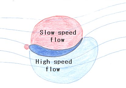
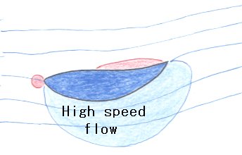
You can see it by watching the flow on the wing top, but if the top of the bodywork is concave, the pressure of the flow increases there.
Wings with recessed top and relatively flat wings are noted below.
The blue space is the low pressure area, the red space is the high pressure area.
In the high pressure region (red), the air current is flowing slowly.
In the low pressure range (blue), the air current is flowing fast.
That is, as the flow velocity decreases, the pressure rises, and when the flow velocity increases, the pressure decreases. Both are a trade-off.
Even if the curvature of the lower surface of the blade is the same shape, in the case where there is a difference in the shape of the upper surface, the air flow path and the aerodynamic performance change greatly.
If the top surface is concave, the high pressure on the top surface contributes to the downforce.
Downforce consists mainly of the sum of the low pressure on the underside of the body structure (wing etc.) and the high pressure on the top.
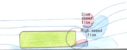
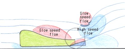
Let's take a look at the difference between the straight shape where the side pod upper surface is not inclined backward and the flow of the shape lowered to the lower side in the F1 machine.
Both are very different.
On the right side of the figure, the upper side of the side pod is inclined rearward, the flow velocity decreases and the pressure is increasing. (Red space)
Since the air current has the property of flowing from high pressure to low pressure, air flow tends to flow toward the rear wing in the right figure.
In the figure below, it is somewhat complicated, but it is a conceptual diagram how the side pod sinking to the rear will become in the actual F1 machine.
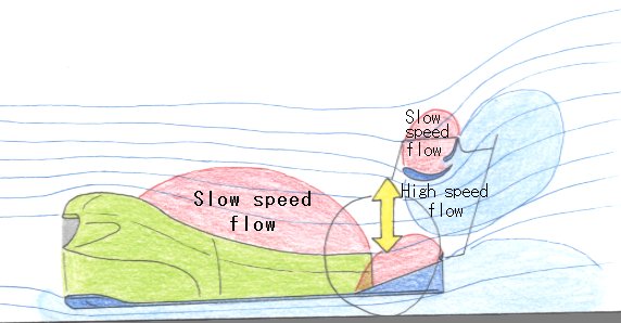
The aerodynamics of the modern F1 machine demonstrates the performance with a slightly complicated but logical and beautiful technique.
Air flow moves from high pressure to low pressure. The pressure distribution shown in the figure is a technique.
The biggest point is focusing on increasing the air extraction amount of the lower surface of the diffuser which contributes the most aerodynamic performance.
The pressure distribution for that purpose is shown in the above figure.
By slanting the side pod upper surface, it is creating multiple merits.
In the above figure, lift has occurred at the front part of the side pod upper surface, but this season Ferrari has been resolved.
However, there is a disadvantage in the concept of the side pod sinking backwards.
If it lowers the rear end of the side pod, it must widen the width to ensure waste heat at the rear end.
If the width of the rear end of the side pod is wide, it reduces the aerodynamic performance of the coke bottle tail.
The low side wide side pod inhibits the aerodynamic performance of the coke bottle in exchange for the pressure merit of the rear wing.
The CFD of each team and the calculation result in the wind tunnel are appearing there.
Who was right answer will be decided by performance on the truck.
(Updated on December 16, 2017)
Congratulations on winning the title.
This year's Mercedes W08 was a very strange machine for me.
The wheelbase is long and the rake angle (the forward tilting posture of the car body) is very shallow.
Why were they doing that?
In brief explanation, "W08" was struggling in the course with many low-speed corners, and it was excellent on a long course with high speed corner and straight.
Considering this result as a short circuit, the power output of the power unit and the length of the wheel base conclude this result.
However, in the F1 GP, since the mid-1990s, the total package of vehicles has become understood as machine performance.
The point I place importance on is the shallow rake angle of W08.
In the time attack game of Suzuka Circuit - machine design called "DOME ambition" of Sony's PlayStation 1 which I was playing in the 90's,
The tire is a slick of Goodyear. In my design, the wheelbase is about 2850 mm,
For the ride height, the front: 20mm / rear: 40mm was the fastest package.
According to the information from modern F1 magazine, the average ride height of each machine seemed to be near the front: 1.5 mm / rear: 6.0 mm.
This ride height (riding height) should have been measured on the extension line of the reference plane.
This year, the range of the flat bottom regulation, the position rearward from the front wheel axle was further defined as 90 mm behind, so we could lower the height of the front car.
As a result, the front wing approaches the road surface, and the effect of the ground effect of the front wing increases.
However, the element I care about in this case is the rake angle, not the ride height.
The author understands that Mercedes who won this year's title won with the excellence of that machine.
It is very interesting what happens to the rake angle of the other team in the 2018 season.
[ Home Page ]

